Antenna Selection for Agricultural Drones: Weight, Vibration, and What the Job Actually Demands
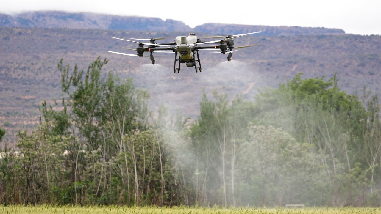
Agricultural drone applications put antennas in operating conditions that most RF components aren’t designed around. The combination of weight constraints, continuous vibration from rotors, exposure to chemical spray, and the need to maintain reliable links across open terrain at speed creates a selection problem that’s more demanding than most stationary agricultural IoT deployments. Getting the antenna wrong on a drone platform means degraded link reliability, reduced effective range, or component failure — any of which interrupts a job that’s being done on a schedule tied to crop conditions.
Weight: why it matters more than it looks on paper
The payload capacity of an agricultural drone is a fixed number, and every gram allocated to supporting components is a gram not available for the spray tank or the sensor suite. Antenna weight is easy to underestimate because individual antennas are small. In practice, a drone with separate antennas for GPS, RTK correction data link, remote control receiver, telemetry, and chemical monitoring can accumulate 150–200 grams in antenna mass plus cable if each antenna is specified independently without attention to weight.
Compact omnidirectional antennas designed for airborne platforms — typically stub or blade designs with low-profile mounting — reduce the per-antenna weight compared to larger ground-mounted options that prioritize gain over compactness. For frequency bands where the efficiency difference between a compact airborne antenna and a full-size ground antenna is small — particularly in the 900 MHz band where the wavelength is manageable — the compact design sacrifices relatively little performance for significant weight savings. At 2.4 GHz and above, the smaller wavelength means compact designs are closer to full efficiency anyway.
The cable run from each antenna to its corresponding radio module is also a weight consideration. Long cable runs add mass and also introduce insertion loss that reduces effective antenna gain. Locating radio modules physically close to their antennas — a design choice that affects the drone’s electronics layout — can reduce cable length, weight, and signal loss simultaneously.
Vibration: the failure mode no datasheet covers
Rotor vibration in agricultural drones is not a minor environmental factor — it’s a sustained mechanical stress that affects every component on the airframe. Antenna connectors are particularly vulnerable because they combine mechanical stress concentration points (the connector-to-cable interface), dissimilar materials with different expansion coefficients, and small-geometry components that fatigue under repeated micro-flex cycles.
SMA connectors, which are common in RF systems at these frequencies, are rated for a limited number of mating cycles and are designed around electrical performance rather than mechanical resilience to vibration. RPSMA and MCX connectors have similar limitations. Connectors that perform well in fixed installations can develop intermittent connections after extended use on a vibrating platform — a failure mode that is difficult to diagnose because the connection tests fine when the system is static but drops out in flight.
Connectors with improved vibration resistance — designs that incorporate positive locking mechanisms rather than relying on friction alone — are worth the incremental cost on drone applications. Coaxial cable with a thicker outer jacket and tighter braid coverage handles repeated flex cycles better than lower-specification alternatives. Where the antenna mounts to the airframe, a mount that dampens rather than transmits vibration extends the antenna connector’s service life.
Frequency allocation in a typical agricultural drone
A fully equipped agricultural drone may use several separate frequency allocations simultaneously. GNSS receivers for position (L1/L2 or multi-constellation) operate in the 1.1–1.6 GHz range. RTK correction data — the differential signal that enables centimeter-level positioning — is often transmitted over a separate radio link in the 900 MHz or 433 MHz band. The remote control link between the ground station and the drone typically operates at 2.4 GHz. Telemetry, which carries flight data and system status back to the operator, may use 915 MHz or 2.4 GHz. Video transmission, where fitted, commonly uses 5.8 GHz.
Each of these frequency allocations needs its own antenna optimized for that band. Using a single wideband antenna to cover multiple functions is an option that simplifies the installation but involves compromises in performance at each individual frequency. For precision agriculture applications where RTK positioning is core to the operation, the positioning antenna and its correction data link antenna should be treated as primary performance components rather than candidates for consolidation.
The Agriculture IoT Antennas used for RTK correction data links on drone platforms benefit from designs optimized for point-to-point link reliability rather than omnidirectional coverage, since the correction data source is typically a fixed base station at a known location. A directional element in the correction data link antenna improves link margin and reduces susceptibility to interference from other sources on the same band.
Spray exposure: the chemical resistance problem
Agricultural drones that apply pesticides, herbicides, or fertilizers operate in a chemical mist environment. Antenna materials that are chemically resistant under normal conditions may degrade when exposed to concentrated agricultural chemicals repeatedly over a growing season. This is a less-discussed selection criterion because most antenna specifications don’t include chemical exposure testing.
The practical risk is not immediate failure but gradual degradation — a radome material that becomes brittle after extended exposure, a connector boot that swells and allows moisture ingress, or a cable jacket that breaks down and allows the chemical to reach the coaxial core. Any of these eventually affects antenna performance or creates reliability problems.
Materials that hold up well include PTFE (teflon) jacketed cables, connectors with stainless steel bodies rather than zinc alloy, and antenna radomes made from UV-stable, chemically resistant polymers such as ASA or PVDF. Verifying that an antenna supplier can speak to the chemical resistance of their materials — not just the electrical specifications — is a useful filter when selecting components for spray drone platforms.
Installation position and airframe interaction
Where an antenna sits on the drone airframe affects its radiation pattern. Ground planes, metallic structural elements, and even the drone’s battery pack can alter the effective pattern and gain of an antenna whose specification was measured in free space. GNSS antennas are particularly sensitive to this: they need a clear view of the sky across a wide elevation angle, and any obstruction in the upper hemisphere reduces the number of satellites in view, which affects positioning reliability.
For RTK correction link antennas, clearance from metallic structures reduces the risk of near-field interaction that can shift the antenna’s resonant frequency away from the intended operating frequency. Mounting antennas on standoffs that position them several centimeters away from metallic mounting surfaces recovers most of the free-space performance for relatively compact installations.
Testing antenna performance after installation on the specific airframe — rather than assuming the component datasheet applies directly — is the approach that actually confirms what the system will do in operation. A quick range test at the beginning of a season, before relying on the system for precision application work, establishes a baseline that makes it easy to detect performance degradation before it affects field operations.